Developing the idea
Who's done what before?
As I said Before, I-m interested in the machines that make paradigm, therefore, I'm focusing on the construction of a machine that will do additive manufacturing. My machine will print with clay. I'm going to use the auger design that many before me have.
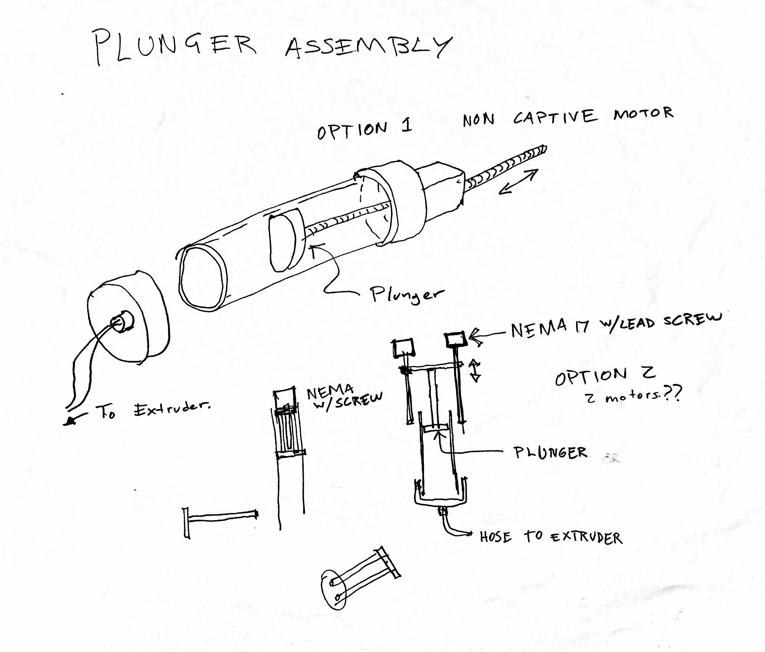
Material is fed onto the work area (1) by a plunger assembly.
What does it do?
The idea is to make a big syringe like object that feeds clay to an extruder. At first I focused on the plunger assembly:
The idea is to make a big syringe like object that feeds clay to an extruder. At first I focused on the plunger assembly:
What parts or systems will be made?
In conclusion, there are 2 basic assemblies.
- Feed Assembly: This will be the syringe that moves clay from a tube to an extruder.
- Extruder Assembly: This will be an auger that pushes clay to the work piece. Motion will be provided from another machine.
Being an architect, I am very comfortable with 3d Design software, but I tried out other new programs like blender for other ideas. That idea no longer is being used, so, I decided to archive it here.
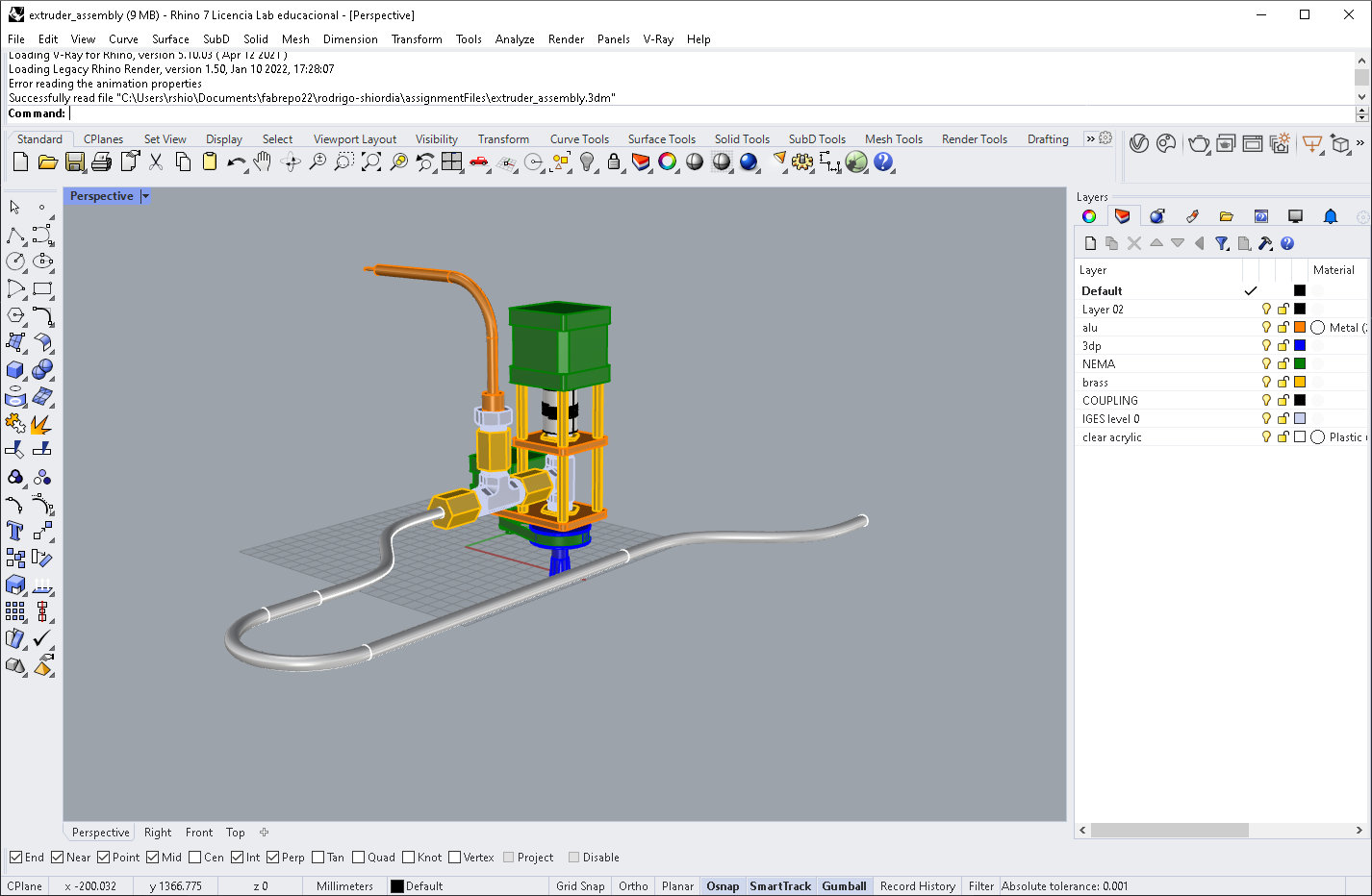
I used Rhinoceros 7 which is a very friendly software to create surface models as well as meshes and solids. Here is a screenshot of how it looks like:
 Main Body Modeling
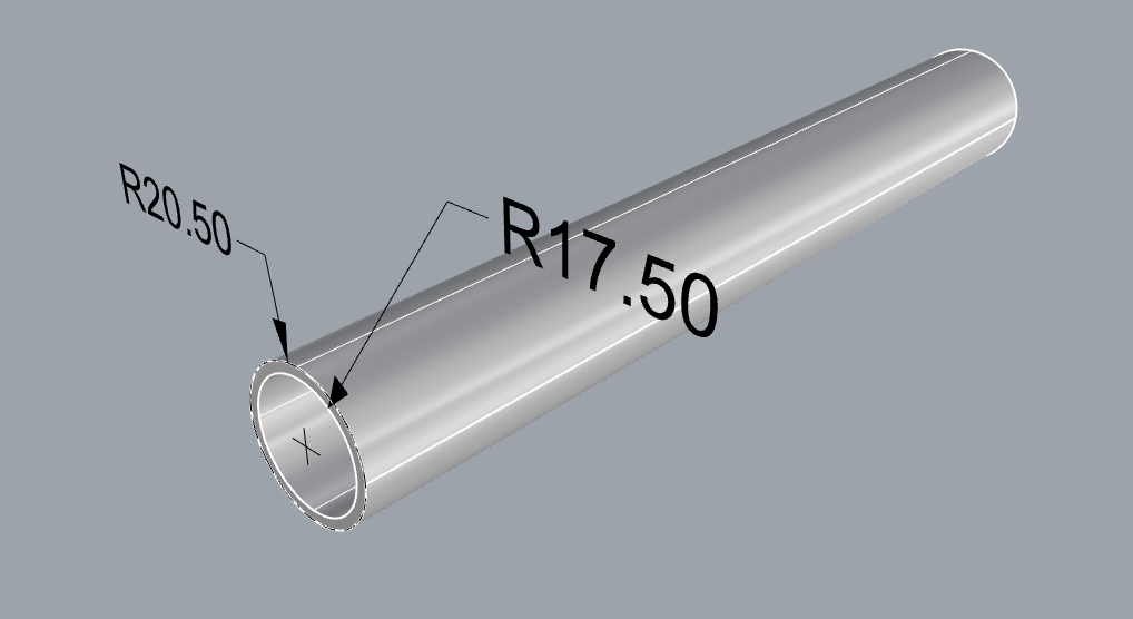
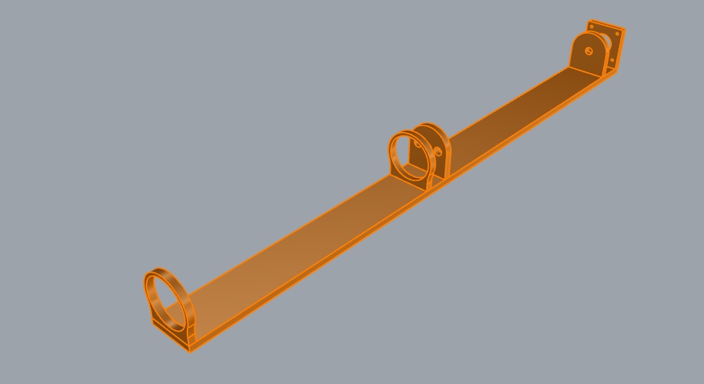
The first part I started with was the tube that will hold the clay. I modelled this part using circle command in Rhinoceros.
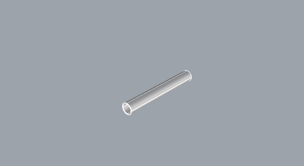
I went to front view, and made the two circles with the appropiate radii, then I used extrude command to make the tube geometry.
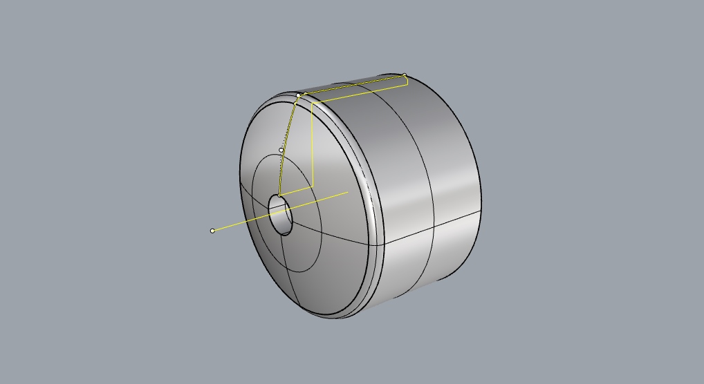
To do the tube cap, I went to side view and drew a polyline with arcs, and lines. I used the fillet command to do some of the trimming and making it into a closed polyline.
After that, I used revolve command around a horizontal line to create te tube cap geometry.
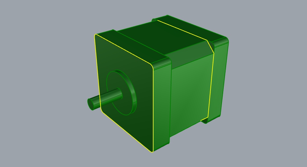
To model the stepper motors, I went to front view and drew rectangle with the measured dimmensions. I again used fillet and chamfer to make the indentations and rounded corners. After that, again, extrude to height.
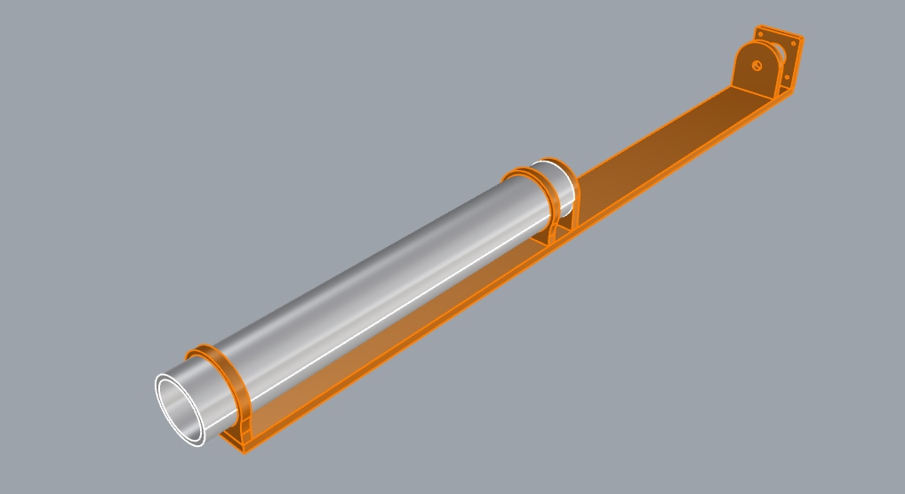
The proposed chassis was just some extrusions, but I had to do booleanDifference to take the geometry of the tube out of the chassis, as well as the rod bearings ansd some other design features.
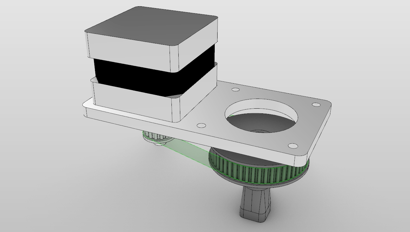
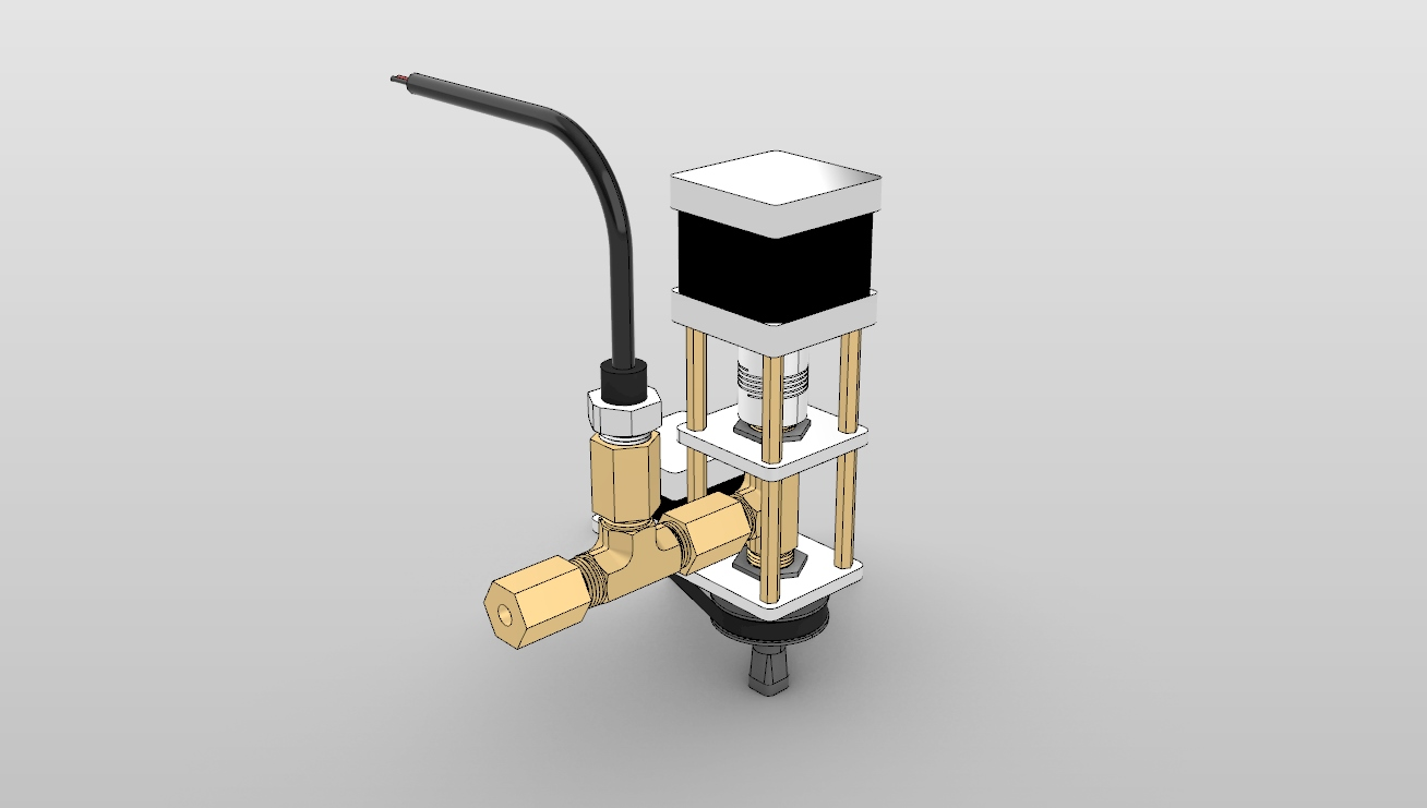
Extruder assembly design
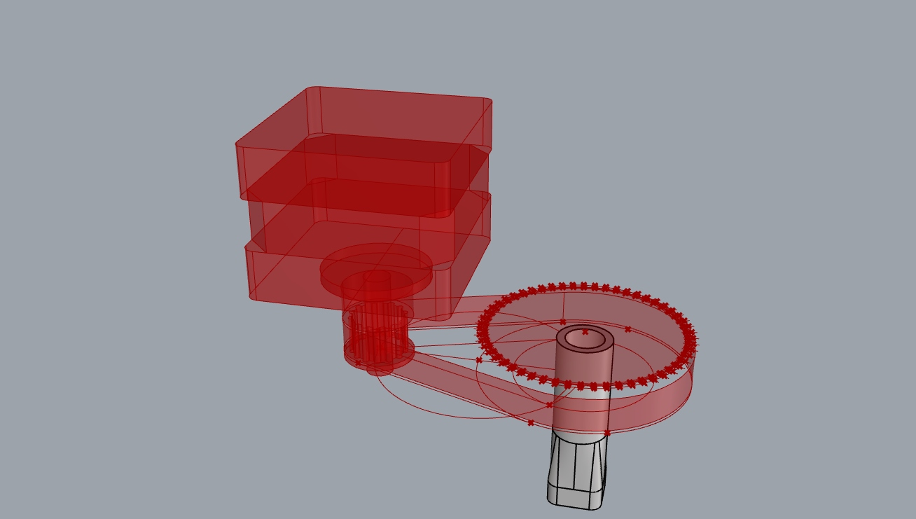
I did a lot of research for finding the correct parts that could be sourced cheaply and locally so the design was heavily influenced by motor sizes. gears and pieces will be 3d printedd and I'll also have an aluminium chassis. This is one of the first sketches:
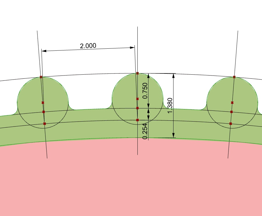
This is an example of how to create the parametric model for a pulley using Grasshopper. I fist created a circle and divided it using the angles from my research.
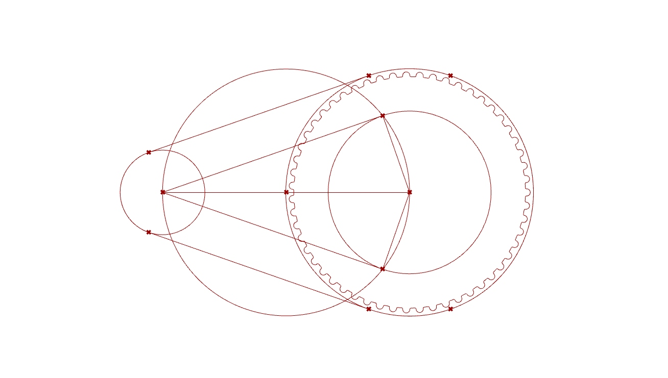
I used arrayPolar in rhino to arrange the teeth in my design.
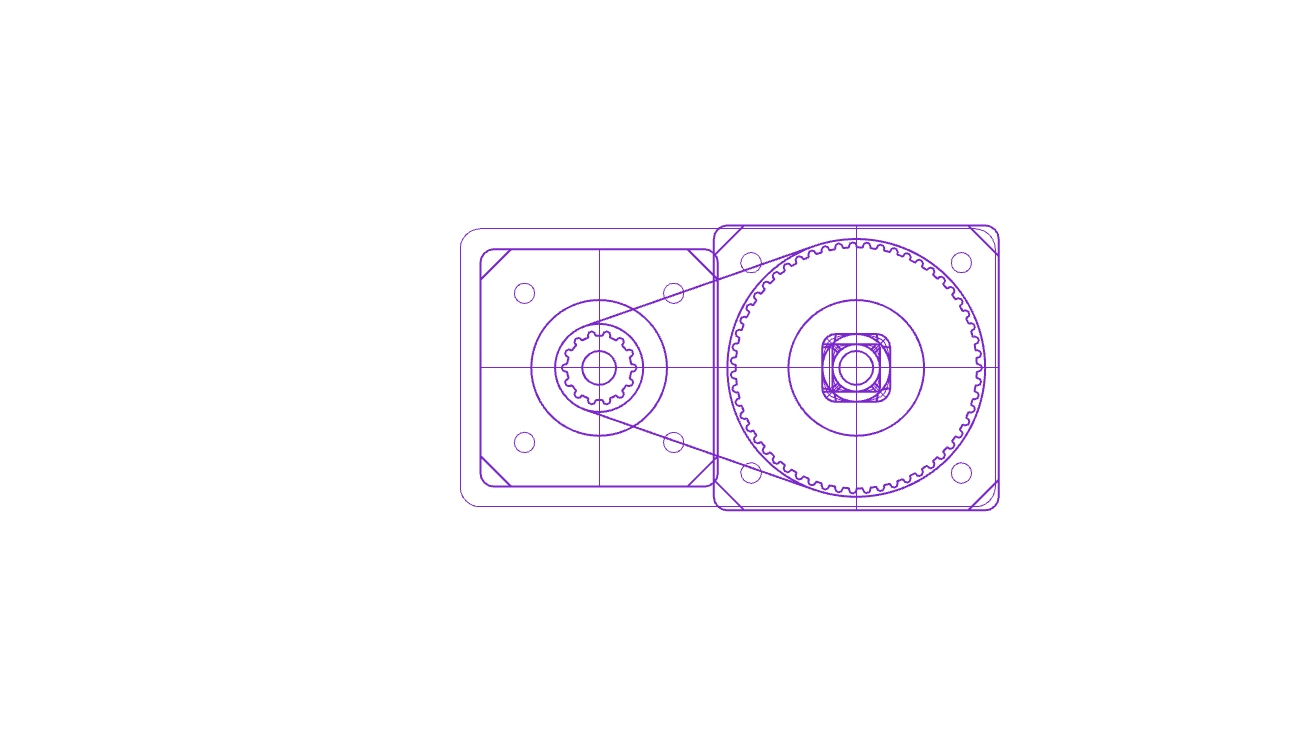
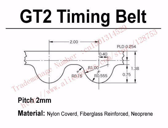
I had to make a paramteric model in order to create the toothed pulleys for the belt I was able to source. I have the spec for the GT2 timing belt, and made a grasshopper file to make the pitch for the tooths exactly identical depending on the belt length and the available space on the design. Here is some of that work: